6.15 Auxiliary boiler fundamentals

6.15.1 Auxiliary boiler and services supplied by steam.

Marine Applications

1.      Tank heating

2.       Marine propulsion

3.       Aux. Eng.

4.       Pumping cargo

5.       Smothering (firefighting)


Above boiler system normally used for the production of saturated steam needed for various services.

The feed water is pumped directly to the oil-fired boiler which is used as a common steam drum for the oil-fired boiler and the exhaust gas economizer.

Steam supplied from the oil-fired boiler steam drum is send to various consumers and return back to the hot well, where the water passes through several filters. Oil tank heating steam drains first come to an observation tank and then flow to the hot well.

Atmospheric condenser is used to condense excess steam produced by the economizer.

Circulating pumps are used to circulate boiler water from the boiler to the economizer.

Atmospheric condenser control the steam pressure while the economizer is in use.

Because of its simplicity and low cost of capital, the above system is widely used and is often entirely adequate when steam production is viewed as a means of meeting the steam demand for heating services on the ship.

Economizer is a water heater which uses energy in main engine exhaust gas to heat water.

6.15.2 Types of boilers

There are two main types of boilers.

  • Fire tube boiler.
  • Water tube boiler

The design and arrangement of both types is just the opposite. In water tube boilers, the water passes through the tubes, and the hot gases pass around them, while in fire tube boilers, the hot gases pass through the tubes and the water around them.


6.15.2.1 FIRE TUBE:

          A fire-tube boiler is a type of boiler in which hot gases from a fire pass through tubes running through a sealed container of water. The heat of the gases is transferred through the walls of the tubes by thermal conduction, heating the water and ultimately creating steam.

6.15.2.2 WATER TUBE:


A water tube boiler is a type of boiler in which water circulates in tubes heated externally by the fire. Fuel is burned inside the furnace, creating hot gas which heats water in the steam-generating tubes.

These boilers can be built to any steam capacity and pressure, Posses higher efficiency and high capacity to size ratio than fire tube boilers.


6.15.2.3 PACKAGE BOILER:


The packaged boiler is so called because it comes as a complete package. Once delivered to site, it requires only the steam, water pipe work, fuel supply and electrical connections to be made for it to become operational. Package boilers may be either water tube, fire tube or coil type. Generally, package type boilers are fully automatic.


6.15.2.4 COMPOSITE BOILER


Composite boiler is a boiler where an oil-fired boiler and an economizer is combined into one unit.

Composite boilers are often used in conjunction with diesel machinery, since if the exhaust gas from the engine is low in temperature due to slow running of the engine and reduced power output; the pressure of the boiler can be maintained by means of an oil fired furnace.  Steam supply can also be maintained with this type of boiler when the engines are not in operation.

6.15.3 Typical pressures of steam produced in auxiliary boilers.

Normally marine auxiliary boilers typical steam pressure is about 7 to 15 bars.


6.15.4 Auxiliary steam boilers range from simple fire-tube boilers to self-contained fully automated package boilers.

(Explain under previous chapters)


6.15.5 Differences between fire tube, water tube and packaged boilers

(Explain under 6.15.2)


6.14 Operations

The content under "Operation" is a general procedure to follow. The manufacturer’s manual must be followed in all cases to understand the machine and type-specific information.

Some of the following may not be applicable or some additional conditions may be applied in actual cases depending on the type and maker.

6.14.1 Purpose of Main Engine Turning Gear and Need for Interlock

The turning gear (T/G) is a device used to rotate the crankshaft of an engine. Turning of the crankshaft is done by turning the flywheel, which is engaged to the T/G. This is a reversible device driven by an electrical motor.

There are a number of purposes for the turning gear:

  • Before starting: It is a safety check to ensure that the engine is free to turn and that no water or oil has collected in the cylinders.

  • After stopping: This helps to evenly distribute the residual heat in the engine, which prevents seizure of the running gears due to difference in contraction.

  • It also prevents the crankshaft from turning due to heavy seas or turbulent waters during stand-still.

  • The turning gear electric motor is connected to an electromagnetic brake to prevent turning of the crankshaft when it is engaged. In addition to the above, its gear box has a very high gear ratio, which also resists turning.

    • Note: Electromagnetic brake is a brake that can be applied or released electrically. Normally it is applied when it is not energized.

  • Working amperage indicates possible hydraulic locking of the engine before starting the engine.

    • Hydraulic lock takes place when a volume of liquid, greater than the clearance volume of the combustion space, is in the cylinder during starting or turning of the engine. As liquid is incompressible, it restricts piston travel during the compression stroke and can damage the cylinder head or connecting rod. This liquid may be cooling water, piston cooling oil, cylinder lubrication oil, or fuel oil.

  • After replacing a bearing, any tightness or resistance to rotate the crankshaft due to any abnormality can be observed by looking at its amperage during turning.

    • If there is any tightness or restriction to rotate, the motor amperage would be increased than normal due to heavy turning load.

  • When an engine overhaul or inspection is carried out, the turning gear is used to turn the engine crankshaft into different positions (e.g., during crank shaft deflection checking, fuel oil timing checking, and bearing clearances checking).

Turning Gear Interlock

The turning gear interlock is a device that prevents the engine from being started if the turning gear is engaged.

What is an interlock?

 An interlock is a feature that prevents operation of equipment until the proper safe conditions are met. The interlock prevents the admission of starting air to the engine cylinders when the turning gear is engaged. If the starting air is admitted with the turning gear engaged, the turning gear will be severely damaged, which may harm nearby personnel. Thus, the interlock is necessary.

6.14.2 Safety checks before turning the engine on turning gear.

Need to follow the instructions given by the engine manufacturer regarding the turning gear for type-specific instructions. The following is a common guideline:

When the engine was stopped, before engaging the turning gear, the main Starting air valve has to be completely closed and drained off the staring airline.

  1. Indicator cocks must be opened. (Indicator cock is fitted on the cylinder head, which opens the cylinder interior to the outer atmosphere).

    • This indicates any liquid filling in the cylinder; if any liquid comes out, the cause must be investigated and rectified.

    • Opening the indicator cock prevents air compression in the cylinders and reduces T/G motor load.

    • Propeller clearance must be taken in writing from the navigation department. (Propeller clearance means taking written permission from the duty navigation officer to rotate the main engine crankshaft without any obstruction or damage to the propeller, external objects, or personnel).

      2.Check that all safety devices which are incorporated into the turning gear are                          functioning properly.

Safety devices include the interlock to prevent starting air opening when the T/G is engaged and the position locking safety pin, which prevents accidental engagement while the engine is in operation.

       3. Make sure that there are no personnel in the crank case.

       4. Make sure that no tools, devices are left on or in the engine after                                         any maintenance on the engine.

        5. Need to ensure correct lubricating oil level and grease where necessary points in                the turning gear device.

Check the safety alarms / trips are in operating condition and reset all, such as:

  • Lube oil Pressure / temperature.

  • Cooling water pressure / temperature

  • Fuel oil pressure / temperature.

  • Emergency shut down.

  • Other applicable

Example: Press the EMERGENCY STOP button on the control panel and observe if the safety cut-out on the fuel injection pumps reacts. After this check, press the EMERGENCY STOP RESET button.

6.14.3 Engine Operation

6.14.3.1 Procedure for Preparing the Engine for Starting

Follow the pre-check list (departure check list) for starting of the engine as per the ISM check list. Before starting, the engine operator’s manual should be read and understood for the recommended procedure and type-specific requirements.

Generally, the above-mentioned checks and procedures must be followed as guidelines:

  • All components that have been overhauled should have been correctly reassembled and their functions checked when trying out the main engine. All devices and tools must be removed from the engine.

    • Examples: Injector – feel the jerk of the high-pressure line; Exhaust v/v – check the valve rotation.

  • Check the liquid levels of all the tanks in the engine systems including the leakage drain tanks, such as:

    • Fuel oil service / settling tank level & temp.

    • Lube oil sump tank.

    • Cylinder oil daily consumption tank level.

    • Expansion water tank level.

    • Intermediate bearing lube oil level.

    • Stuffing box drain tank level.

    • Scavenge drain tank level.

    • Fuel drain tank level.

    • Piston cooling water tank.

  • Check that the fuel regulating linkage moves freely.

  • If any maintenance was carried out in the oil / water systems, those should be vented for air before putting into operation.

  • Start an additional generator and couple it to the main bus bar to provide power for the extra loads.

Check that all the shut-off valves for the engine systems are in the correct position. (e.g., jacket water system valves).

  • Check the engine cooling water system and start the pump. Required checks:

    • Cooling water header tank level.

    • Any leakages in the system.

    • Cooling water engine inlet temperature.

    • Cooling water system general condition.

  • Prepare the lube oil system and start the pump. Required checks:

    • Header tank level.

    • Lube oil fine filter condition indicator and pressure.

    • Any leakages in the system.

    • Lube engine inlet temperature.

    • Lube oil system general condition.

  • Prepare the fuel system and drain the water in fuel oil service and settling tank. Check the engine fuel oil system and start the pumps. Required checks:

    • Service / settling tank level / temperature.

    • Fuel oil fine filter condition and pressure.

    • Fuel circulating and supply pump filter condition, pressure, and leakages.

    • Fuel viscosity and engine inlet temperature.

    • Fuel oil system general condition.

  • Before Opening the air supply to the engine, drain the condensation from:

    • Main air bottle.

    • Air dryers.

    • Control air filters.

  • Start up the other systems such as cylinder lubricating system pumps and check/set the pressures to their normal values.

  • Start preheating of the main engine by opening the jacket water to the jacket water preheater and then open steam slowly.

  • Check all the systems for any leakages and operate within normal parameters.

  • Start cylinder pre lubrication.

  • Confirm that all indicator cocks in the engine are opened.

  • Turn the engine more than one revolution using the turning gear and check the motor amperage.

  • Check while turning if any liquid is coming through the indicator cock. If so, investigate the cause (e.g., leaking jacket water, fuel oil from injectors).

  • If even a small amount of liquid comes out of any of the indicator cocks, the T/G must be immediately stopped and the reason investigated/rectified.

  • Take out the turning gear and secure the operating lever.

  • Open the main air shut-off valve on the main air bottle.

  • Set the auxiliary blower control panel selector switch to the automatic position.

  • Check main cooling seawater system and start the pumps. Required checks: Filter condition, pump pressure, and system general condition.

  • Check the boiler and keep it in an automatic position. Required checks: Steam pressure, water level, burner flame condition.

  • Check the other systems related to the main engine and propulsion (e.g., steering gear, control air, stern tube).

  • Select all air compressors to auto mode.

  • Check again to ensure that no personnel are near the flywheel and shaft.

  • Inform the bridge and the duty engineer.

6.14.3.2 Engine Starting

Before the engine is on standby, the engine must be tested on air and fuel by means of ahead and stern direction running after following conditions are full filled:

  • Gradually open main air bottle valve to the main engine.

  • Shut off valve to the air distributor must also be open, if applicable.

  • All the systems related to main engines are in operating condition and stand by condition, free of alarms, shut down and slow down.

  • Inform the bridge and, with their permission, air blow must be done in the control room, monitoring the indicator cocks for any leakages during blow through.

    • If there is fuel, cylinder oil, cooling water or cooling oil leakages, these will be indicated when blowing through. In such a case operation must be immediately stopped.

    • Blow through means introducing starting air to the engine cylinders for a short period while indicator valves are opened.

  • If everything is satisfactory, indicator valves to be closed and inform the duty engineer.

  • Try out (check ahead and stern operation of the main engine) the main engine by fuel in either direction. (If M/E bridge control is available, it must be tried out from the bridge as well).

  • Inform the bridge on official standby of the main engine and change over to bridge control. Get the standby counters as required (Fuel oil flow meter, revolution counter, cylinder oil flow meter, etc.).

6.14.3.3 Procedure for Operating the Main Engine

It is preferable to operate the engine at constant power. When the speed and load have to be altered, it should be done as slowly as possible, especially after engine maintenance. During normal running, regular checks have to be made:

  • Regular checks of parameters such as pressures and temperatures. The parameters must be within the manufacturer-accepted range.

  • Liquid flow through sight glasses (Ex. T/C lube oil).

  • Check all systems related to the engine are functioning correctly. Including Pumps, filters, pipelines, and the related systems.

  • Check combustion by observing the color of the exhaust gases.

  • Check the air pressure charge drops through the air filter and air cooler. Excessive resistance will lead to a lack of air to the engine.

  • The fuel has to be carefully cleaned before being used. Open the drain cocks of all fuel tanks and fuel oil filters regularly to drain off any water.

  • Have to regularly monitor and clean the fuel filters according to their differential pressure.

  • Fuel oil service and settling tank temperatures to be correct.

  • Maintain the correct fuel oil pressure and the temperature to inlet the engine.

  • Check that all cylinder lubricators are functioning well.

  • Check the level in all water and oil tanks, as well as all the drainage tanks.

  • Observe the condition of the cooling water. Check for oil contamination.

  • Sight glass is provided in charge the air receiver drains manifolds. Make sure it is clear at all times.

  • Drain the scavenge spaces.

  • The temperature of the running gear should be checked by feeling the crankcase doors. Bearings that have been overhauled or replaced must be given special attention.

  • Listening to the noise of the engine will reveal any irregularities.

  • Centrifuge the sump lubricating oil.

  • Check the inspection glasses in the upper casing of the exhaust valve periodically and note if the air spring cylinder of each exhaust valve is rotating.

  • Avoid critical RPM.

6.14.3.4 Stopped

After the engine has been stopped, the cooling water and lubricating oil pumps should be left running for at least a further 20 minutes in order to allow the temperatures to equalize.

  • Take the main engine control from Bridge to Engine Control Room (make sure fuel lever is in zero position).

  • The starting air supply has to be closed as soon as possible after stopping the engine.

  • The indicator cocks in the cylinder heads are to be opened and the turning gear to be engaged.

  • With post lubrication of the cylinders, the crankshaft must be turned by the turning gear.

  • Turn the engine around 20 minutes after stop. This helps to evenly distribute the residual heat and prevents seizure.

  • Let the cooling water to cool gradually, otherwise sudden cooling may result in thermal stress.

  • Lubricating oil pump should be continued to run for at least a further 2 hours in order to allow the temperatures to equalize gradually.

  • Stop the unnecessary equipment and inform the engineers and crew.

6.14.3.5 Reversed when maneuvering and when at full speed

6.14.3.5.1 Reversing a Slow Speed Engine

The propeller thrust must be reversible for maneuvering and to crash stop the ship. Most vessels require the main engines to be reversible.

  • Start and load additional power generator.

  • Change engine control to the engine control room.

  • Where manually operated auxiliary blowers are fitted, they should be started.

  • Bring the telegraph to stop position.

  • Shift the fuel level to the stop position. (Engine RPM will reduce).

  • Wait until the RPM of the engine becomes zero.

  • Then bring the telegraph to dead slow astern position.

  • Shift the fuel level to the starting position. (Air will introduce to the engine and crankshaft will rotate to astern direction).

  • When the correct starting RPM is reached, stop starting air and introduce fuel to the engine.

  • Check the running direction.

  • Adjust the fuel lever to maintain correct speed.

6.14.3.5.2 Crash Maneuvering of Ship in Emergency Situation

"Crash maneuvering" is a procedure performed to avoid any kind of collision or accident. Stopping is done by reversing the rotational direction of the Main engine and thereby the propeller.

6.14.3.5.3 Perform Crash Maneuvering

  • Change engine control to the engine control room.

  • Start and load additional power generator.

  • Where manually operated auxiliary blowers are fitted, they should be started.

  • Bring the telegraph to stop position.

  • Shift the fuel level to the stop position. (Engine RPM will reduce).

  • Wait until the RPM of the engine reduces to 40.

  • Then bring the telegraph to Full Astern position.

  • Shift the fuel level to the starting position. (Air will introduce to the engine).

  • When the correct starting RPM is reached, stop starting air and introduce fuel to the engine.

  • Check the running direction.

  • Adjust the fuel lever to maintain correct speed.

  • Note: Crash astern may damage the engine due to thermal shocks as the engine is cool and heats rapidly. To be used only when extremely required.

6.14.4 How engine speed and output power are controlled for normal requirements.

A governor automatically controls engine speed by regulating the fuel supply. The governor must be sensitive to small changes in speed and capable of returning the engine to a set speed, irrespective of changes in load and power.

6.14.4.1 Main types of governors described below:

6.14.4.1.1 Mechanical Governor

As shown in the figure below, 

  • A flyweight assembly is used to detect engine speed. Flyweights rotate about a vertical axis.

  • Centrifugal force throws the weights outwards, which lifts the vertical spindle and compresses the spring until an equilibrium situation (set speed) is reached.

  • The hydraulic unit is connected to this vertical spindle and acts as a power source to move the engine fuel controls.

  • If the engine speed increases, the vertical spindle rises, oil is drained from the power piston, and the resulting movement reduces the fuel supply to the engine, slowing it down.

6.14.4.1.2 Electric Governor

The electric governor uses a combination of electronic and mechanical components.

  • Shaft speed is sensed by the speed pick up, and this pulsating signal is converted to voltage and sent to the comparator.

  • The comparator compares the present value with the set value and gives a signal to the amplifier.

  • The amplifier provides enough power to the actuator (Final control element) to move the fuel lever of the engine to get the speed back to the set value.

6.14.5 How engine over speed is prevented

Due to sudden changes in load, the speed of the engine may vary. Although a governor controls speed, the speed might still go out of control, damaging the engine. Thus, over speed trips are used.

The main aim of the over speed trip is to cut the fuel supply to the engine cylinders in case the engine speed rises above a specific level (typically 12% - 18% above rated speed).

Types of Over Speed Trips:

  • Mechanical Type Over Speed Trip

  • Electrohydraulic Overspeed Trip

  • Electro Pneumatic Over Speed Trip

  • Electronic Type Over Speed Trip

6.14.5.1 Mechanical Type over speed Trip

A simple mechanical over speed trip has a weighted spring-loaded bolt set into the rotating shaft of the engine.

  • The centrifugal force exerted on the bolt exceeds the preset spring force when speed exceeds the limit.

  • The bolt ejects out and strikes a latch, which releases a plunger that shuts off the fuel supply to the engine.

6.14.6 States Typical Normal Temperatures of Exhaust Gas at Discharge from the Cylinder

The temperature measured at the exhaust valves is normally in the range of 320-400 °C at MCR (Maximum Continuous Rating), depending on ambient conditions.

6.14.7 States Typical Normal Temperatures of Exhaust Gas Entering & Leaving a Turbo charging Unit.

Normal Temperatures of exhaust gas entering and leaving a turbocharger unit:

  • Inlet (Entering): 380 – 450 °C

  • Outlet (Leaving): 270 – 320 °C

6.13. Engine Systems

6.13.1 Engine systems

6.13.1.1 Fuel oil systems

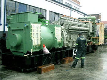
Large marine diesel engines consume a large amount of fuel oil. Therefore, it is not economical to run them continuously on diesel oil. Marine engines are normally operated on Heavy Fuel Oil (HFO), which is cheaper than diesel. Diesel oil is also available onboard to use in special situations.

Heavy fuel contains a lot of impurities such as sludge and water. Therefore, it has to be treated before use. On top of that, heavy fuel viscosity is also very high, so viscosity has to be reduced in order to treat, pump, and consume it effectively.

Fuel to be used is first transferred from storage tanks to a settling tank in which it is heated to allow some water and sludge to settle out by gravity and be drained off. The fuel is then passed through a centrifugal separation system and discharged to a daily tank (service tank).

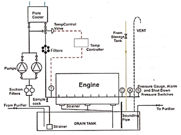
Fuel oil system with flow indication.

From the daily service tank, the oil flows through a three-way valve to supply pumps via a filter. These supply pumps supply fuel into mixing tanks (buffer tank) via a filter which removes impurities in the fuel oil. The mixing tank assists in the gradual mixing of HFO and Diesel oil during changeover, helps to purge air from the system, and also provides a constant pressure head to the system.

A flow meter is fitted before the mixing column to indicate fuel consumption. Booster pumps or circulating pumps are used to pump the oil through heaters and a viscosity regulator (viscotherm) to the engine fuel pumps. There is a fine filter immediately before the fuel pumps to remove fine impurities. The fuel pumps provide high-pressure fuel to their respective injectors.

The viscosity regulator or viscotherm varies the fuel oil temperature in order to provide the correct viscosity for combustion. Fuel oil is heated by steam in fuel oil heaters. A return line pressure control valve ensures a constant-pressure supply to the fuel pumps.

Excess fuel from the engine fuel pumps is returned back to the buffer tank, but provision is provided to divert return oil to the service tank. A diesel oil daily service tank may be installed and is connected to the system via a three-way valve. Relief valves are used to release excess pressure.

  • Primary or supply pump pressure is about 4 bar.

  • Circulating or booster pressure is 10/12 bar.

6.13.1.2 Lub oil systems

The lubrication system of an engine provides a supply of lubricating oil to the various moving and rotating parts in the engine. Its main function is to enable the formation of a film of oil between the moving parts, which reduces friction and wear. The lubricating oil is also used as a cleaner and as a coolant.

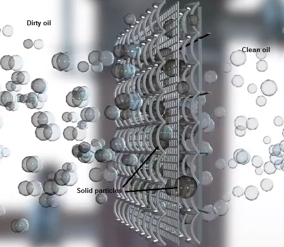
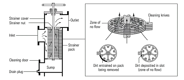
Lubricating oil for an engine is stored in a drain tank located beneath the engine. The oil is drawn from this tank through a strainer by a lube oil pump. The oil is then passed through a cooler and a Temperature control valve which regulates flow through the cooler to maintain the oil at the correct temperature (and therefore viscosity) at the inlet to the engine. Then the oil is sent through a fine filter before sending it to the engine in order to remove fine impurities. A Sample Cock enables drawing off a sample for analysis.

6.13.1.3 Piston cooling system

Marine diesel engines have a number of cooling systems to maintain optimum operating temperatures. One of these systems is the piston cooling that is achieved using either oil or water as a cooling medium. Originally, water was preferred; however, modern diesel engines mostly use oil.

6.13.1.3.1 Piston cooling oil system

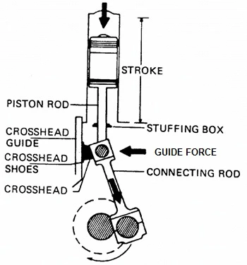
The oil is drawn from the main engine sump by the lube-oil pump, being discharged to a manifold bolted to the outside engine casing. From here, an internal swinging arm piping system supplies oil to the crosshead bearing and the piston cooling.

The cooling oil is delivered to the piston crown, through the center of the hollow piston rod, circulating through the cooling channels in the piston. The oil returns through the piston rod via small holes, where it is collected in a tray at the crosshead bearing. Here the oil temperature is monitored before spilling over the tray, cascading down into the main lube-oil sump.

6.13.1.3.2 Piston cooling water system

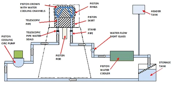
A centrifugal pump supplies the cooling water under pressure to the piston, where it is circulated through water channels that have been cast into the piston.

The water enters and leaves the piston through telescopic pipes that slide up and down on standpipes as the piston reciprocates. The water temperature is maintained by a dedicated seawater cooler, and a header tank allows the system water and additive to be topped up and also provides a positive head to the system.

A cooling water storage tank is in the system; here the water flows into the tank from the return line, where it passes through a filter plate. The cooling water pumps then draw the water from here, circulating the water through the pistons and cooler.

6.13.1.4 Jacket Cooling Water

The cooling water pump (which may be engine driven or a separate electrically driven pump) pushes the water around the circuit. After passing through the engine, it removes the heat from the cylinder liners, cylinder heads, exhaust valves and sometimes the turbochargers. It is cooled by seawater and then returns to the engine. The temperature of the cooling water is closely controlled using a three-way control valve.

The cooling water outlet temperature is usually maintained at about 80-85C.

A Header tank is used to provide pressure head to the pump, and it makes up any system losses. Vents from the system are also led to this header tank to allow for any expansion in the system and to get rid of any air. The header tank is deliberately made to be manually replenished and is fitted with a low-level alarm. This is so that any major leak would be noticed immediately.

The system will also contain a heater which is to keep the cooling water hot when the engine is stopped, or to allow the temperature to be raised to a suitable level prior to starting. A freshwater generator (FWG), which is used to produce fresh water from sea water, is also incorporated into the jacket water system.

A drain tank has been included. This is to drain the engine cooling water for maintenance purposes. Because of the quantities of water involved and the chemical treatment, the water can be reused.

6.13.1.5 Cooling of fuel valve

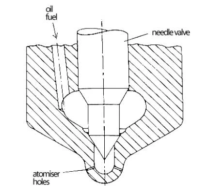
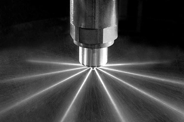
When burning heavy fuel oil, Nozzle cooling is required as injectors are exposed to high temperature during combustion.

Some injectors have internal cooling passages in them extending into the nozzle through which cooling water is circulated. This is to prevent overheating and burning of the nozzle tip.

The water is circulated from a tank via a pump, cooler, and cooling spaces in the injector nozzle tips before being returned to the tank via individual return pipes. The tank is equipped with a heating coil to maintain the water temperature at 70C when the engine is stopped. An observation window is provided as a means of checking that the tank is clear of fuel oil contamination. If contamination occurs, the faulty injector can be identified by taking samples from the individual returns. Some cooling systems use oil as the coolant.

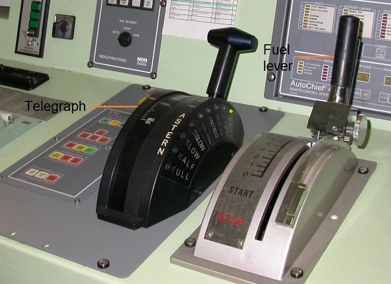
6.13.1.6 Starting air system

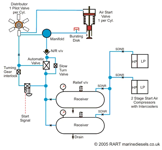
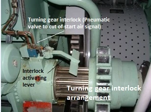
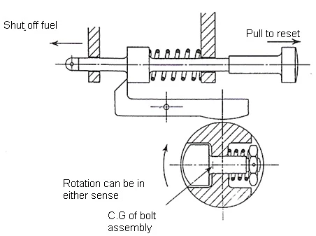
Diesel engines are started by supplying compressed air into the cylinders in the appropriate sequence for the desired rotating direction. A supply of compressed air is stored in air reservoirs or 'bottles' ready for immediate use. The starting air system usually has interlocks to prevent starting if everything is not in order (e.g., if the turning gear is engaged).

Compressed air is supplied by air compressors to the air receivers. Then it is supplied by a large bore pipe to a remote operating automatic valve and then to the cylinder air start valve. The automatic valve is only open whilst an air start is taking place. The air start valve is located in the cylinder head, and its purpose is to supply starting air into the cylinder.

The opening of the air start valve is controlled by a pilot air system. The pilot air is supplied in the correct sequence by the starting air distributor.

  • A Bursting disk is present to burst in case of excess pressure in the starting air manifold.

  • A Non-Return (N/R) valve is to prevent back flow of hot gases to the starting air bottles in case of a starting airline explosion.

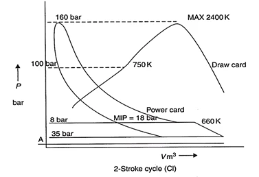
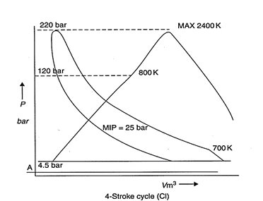
6.13.1.7 Scavenge Combustion Air and Exhaust Passage

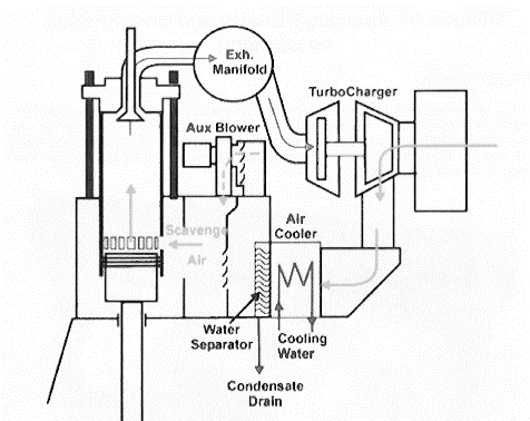
Scavenging is the process of removing exhaust gases from the cylinder after combustion and replenishing the cylinder with fresh air.

The exhaust gas is sent to the exhaust manifold via exhaust valves. This exhaust gas is used to drive the turbocharger (Turbo charger is explained under 6.11). The turbocharger gas outlet goes to the funnel via the economizer.

Fresh air drawn through the turbocharger filter is compressed and sent to the scavenge air manifold via a cooler. (When the air is compressed, its temperature increases, thus reducing its density. Therefore, cooling is necessary in order to increase the density of air.) Then scavenge air is sent to the under-piston space via non-return flaps or valves.

The scavenge air enters the cylinder through the scavenge ports in the lower part of the cylinder liner.

6.13.2 Sketches an air reservoir, identifying all of the fittings.

Air Bottle Mountings and Connections

The general mountings and connection present on the air bottle of a ship are:

  • Filling valve: This is a valve fitted in the supply connection from the main air compressor to the air bottle.

  • Outlet to Main engine: An outlet valve and pipe is fitted for connection from the air bottle to the main engine for supplying air during starting. This is a slow turning screw down valve.

  • Outlet to auxiliary engine: An outlet valve and pipe is fitted for connection from the air bottle to auxiliary engines for supplying air during starting.

  • Auxiliary connection: Other auxiliary supplies connections such as service air, safety air, etc., are also provided with an isolating valve.

  • Relief valve: A relief valve is fitted on the air bottle to relieve excess pressure inside the bottle. Normally this is let to the outer atmosphere.

  • Drain valve: A drain valve is fitted at the bottom of the bottle to drain accumulated condensate from the receiver.

  • Fusible plug: A fusible plug is fitted in the bottle with a separate connection leading out of the engine room so that in the event of fire, this plug will melt and relieve all air to the outside the engine room.

  • Manhole door: A manhole door is fitted in the bottle to carry out inspection of the same.

6.10. Engine Power Measurement

6.10.1 Sketches typical indicator diagrams for:

6.10.1.1 A two stroke engine

Typical indicator diagrams for a two-stroke engine show the work done within the measured cylinder in one cycle. The area within the diagram represents the work done. This area is divided by the length of the diagram to obtain a mean height. This mean height, when multiplied by the spring scale of the indicator mechanism, gives the Indicated Mean Effective Pressure (MEP) for the cylinder.

Key points on the diagram:

A. Ignition

B. Pressure-Volume Working Diagram

C. Ignition Stroke

D. Draw Diagram

E. Top Dead Centre (TDC)

F. Bottom Dead Centre (BDC)

G. Pcomp

H. Pmax

I. Opening of Exhaust Valve 

6.10.1.2 A four stroke engine

6.10.2 Explains the problems of obtaining indicator diagrams from slow-speed, medium-speed and high-speed engines

An engine indicator which is suitable for taking indicator diagrams is typically reliable up to rotational speeds of about 300 rev/min.

For medium-speed and high-speed engines, it may be impractical to use a normal engine indicator due to the high velocities of parts causing vibrations in springs or drive mechanisms. If other means are not available, power in the engine may be related to peak or maximum pressure in the cylinder.

Generally, only slow speed engine builders provide mechanical indicator drum drive mechanism in the engine.

6.10.3 Peak pressures are sometimes measured which give an indication of engine power and performance

The power in the engine is related to the peak or maximum cylinder pressure; this is measured using a peak pressure indicator. This can be a mechanical device, using compression of a spring to indicate pressure or a pressure transducer linked to a digital read out. This should be done at between 85 -100%  MCR (Maximum Continuous Rating). It is more accurate to use the difference between the peak and the compression pressure when assessing cylinder powers and attempting to balance the engine.

In small engines, only the peak pressure is measured, and it is an indication of power and performance of the engine unit.

6.10.4 Develops the expression: work = pressure x volume, to produce an expression for the power of a diesel engine in terms of M.E.P., number of cylinders, length of stroke, diameter of piston and R.P.M.

Force

Force is the influence, which tends to change the motion or direction of a body at rest or in motion.

Force = Pressure x Area

             Nm^{-2} x m^2

             N

Force is measured in Newton (N)

Work

Work is the use of energy to overcome resistance. Work is done when a force is applied on an object to move it through a distance.

Work = Force x Distance

             N x m

               Nm

Since Force is measured in Newton (N) and distance in metres (m), the units of work are Newton metres (Nm).

One Newton metre is defined as one Joule (J). Joule: It is equal to the energy transferred (or work done) to an object when a force of one newton acts on that object in the direction of its motion through a distance of one meter (1 Newton meter or N.m).

Power

Power is the amount of work done or energy expended in a given time. A Watt (W) is the unit of measurement of power.

One watt is defined as the energy expended or work done at the rate of one Joule per second.

Power = Work                   =        Force x Distance (Joule)

 Time                                    Time (second)

Indicated Power (IP) Expression

The mean effective or 'average' pressure (MEP) can now be used to determine the work done on the cylinder:

Work per Cycle = MEP x Area x Stroke Length

To obtain a measure of power, it is necessary to determine the rate of doing work, i.e., multiply by the number of power strokes in one second.

The indicated power is calculated using the mean effective pressure.

IP = P x L x  A x N

Where:

  • IP = Indicated power (Watts) {1kW = 1000 Watts}

  • P = Mean effective pressure (kg/cm^2)

  • L = Length of piston stroke (Meters)

  • A = Cross sectional area or cylinder bore (Square meters)

  • N = Number of working strokes per second (revs/second)

For a multi-cylinder engine, it would be necessary to multiply the result by the number of cylinders.

6.10.5 Calculation of indicated power

Given Data:

  • Area of diagram = 840 mm^2

  • Length of diagram = 105 mm

  • Mean height of diagram = 8 mm

  • Spring constantly = 200  kN/m^2 per mm

  • Diameter of cylinder = 960 mm (Radius 0.48 m)

  • Stroke of piston (L) = 2.5 m

  • Engine Speed = 90 RPM = 1.5 revs/sec

Step 1: Calculate Mean Indicated Pressure (MIP or P)

MIP = 8 x 200 = 1600N/m2

Diameter of cylinder= 960 mm (radius 0.48m)

Stroke of piston = 2.5m

Step 2: Calculate Work per Cycle

Work per cycle (or revolution) = 1600 x π x 0.48x0.48 x 2.5 = 2895 kNm or kJ

Step 3: Calculate Indicated Power (IP).

E. G. 90 RPM = 1.5revs/sec.

2895 X 1.5 = 4343kW

This process is repeated for each cylinder on the engine.

This process is repeated for each cylinder on the engine to find the total Indicated Power of the engine.

6.10.6 States typical compressions and maximum pressures for slow-, medium- and high-speed engines

Maximum compression pressures for the slow speed engine

Maximum compression pressures for the medium speed engine

6.9 Types of Engines

6.9.1 Engine Categories by Bore and Rotational Speed

Marine diesel engines are normally described in broad categories by the bore of their cylinders and their rotational speed.

  • Bore – refers to the inner diameter of the engine cylinder.

Engines are categorized by the size of the cylinder bore as:

  • Large bore

  • Small bore

Marine diesel engines are also categorized by their rotational speed:

Slow Speed Engine

  • Speed: 70 – 200 rpm

  • Cylinder bore: 500 mm and above

  • Output / Power: 3,000 – 100,000 bhp

Medium Speed Engine

  • Speed: 400 – 1,200 rpm

  • Cylinder bore: 100 – 350 mm

  • Output / Power: 1,000 – 8,000 bhp

High Speed Engine

  • Speed: 1,200 rpm and above

  • Cylinder bore: 130 – 180 mm

  • Output / Power: 250 – 800 bhp

6.9.2 Large-Bore Engines: Piston Rods and Crossheads

Large-bore engines are normally fitted with piston rods and crossheads.

In this design, an additional component called the crosshead is used to achieve the swinging action of the connecting rod and to transfer the horizontal thrust to the cylinder liner. It also guides the piston to move centrally in the liner.

  • The piston is rigidly fixed to the piston rod.

  • The rod passes through a gland to a crosshead to which it is attached via a flange or shoulder through bolt and nut.

  • The crosshead assembly slides up and down in guides.

  • The crosshead assembly is connected to the crankshaft by the connecting rod with bearings.

  • Due to this design, it is possible to achieve a smaller turning radius of the crankshaft, even for large piston strokes.

6.9.3 Smaller Diesel Engines: Trunk Pistons and Gudgeon Pins

Small-bore engines are commonly equipped with only one connecting rod and use a trunk piston and a gudgeon pin in place of a piston rod and crosshead.

  • The piston is connected directly to the upper end of the connecting rod by the gudgeon pin (Piston pin) and bearings.

  • The lower end of the connecting rod is connected to the crankshaft with a bearing.

6.9.4 Large-Bore Engines and Low Propeller Speed

Large-bore engines are normally directly connected to the propeller and therefore rotate at low speed.

Propeller efficiency is highest when the propeller speed is low. As large-bore engines are directly connected, the engine RPM must also be lower to gain high efficiency.

6.9.5 Other Diesel Engines and Duties

Other diesel engines may run at medium speed or high speed, depending upon their duty. These engines serve various auxiliary and emergency roles on a vessel.

Some examples of applications for these engines include:

  • Lifeboat engines

  • Main / Emergency power generation

  • Emergency fire pump prime movers

  • Emergency air compressor

  • Cargo pump prime movers

  • Hydraulic power packs

6.9.6 Medium-Speed and High-Speed Engines for Electrical Power

Medium-speed and high-speed engines are often used as direct drives for the generation of electrical power.

  • The medium-speed four-stroke trunk piston engine can be found on large merchant vessels, even if the main engine is a two-stroke crosshead engine. In these cases, they supply the electrical power by driving alternators.

  • Medium-speed engines (300 - 1200 rpm) are common for smaller ship propulsion and power plants driving electrical generators.

  • High-speed engines (approximately 1,000 rpm and greater) are typically used for small electrical generators.

6.9.7 Medium-Speed Engines as Main Propulsion (with Reduction Gear)

Medium-speed engines (and occasionally high-speed engines) are used, through some form of speed reduction, as main propulsion engines.

Need for a Reduction Gear:

  • The optimum rotational speed of a medium-speed engine is 300 to 1500 RPM.

  • This speed is higher than the optimum propeller speed for high efficiency.

  • In order to improve the overall performance of the energy conversion system, reduction gears are fitted to enable both the engine and the propeller to work efficiently.

Gearing is used to transmit power in a drive line at a different rotational speed than the prime mover, which also changes the transmitted torque. A gearbox reduces the rotational speed, allowing the prime mover to run at its optimum design speed while the propeller operates at its optimum, lower speed.

6.9.8 Approximate Speed Range Comparison

comparision of different speed engines

Slow speed (up to 150rpm)

Medium speed (up to 1000rpm)

High speed (above 1000rpm)

6.8 Fuel Treatment

6.8.1 Filters Used in Fuel Lines

Mechanical separation of solid contaminants from various systems (fuel, lubricating oil, etc.) is achieved by the use of filters and strainers.

6.8.1.1 Strainers

A strainer is a device used to separate unwanted solids from a liquid by filtering. A strainer should be cleaned as soon as it is taken out of the system, then reassembled and left ready for use.

6.8.1.2 Gauze Filter

The strainer usually employs a mesh screen, an assembly of closely packed metal plates, or wire coils which effectively block all particles. It is typically fitted on the suction side of a pump to prevent damage to the pump components due to unwanted solid particles. The particles of dirt collect on the outside of the strainer element or basket and can be removed by compressed air or brushing.

6.8.1.3 Edge – Type Packs

The edge-type pack is an improvement on the simple wire gauze mesh strainer and can be cleaned whilst in operation, filtering out very small particles.

  • The dirty oil passes between a series of thin metal discs mounted upon a square central spindle.

  • Between the discs are thin metal star-shaped spacing washers of slightly smaller overall diameter than the discs.

  • Cleaning blades, fitted to a square stationary spindle and the same thickness as the star-shaped washers, are located between each pair of discs.

  • As the oil passes between the discs, solid particles larger than the spacer between the discs remain upon the periphery of the disc stack.

  • The filter is cleaned by rotating the central spindle; this rotates the disc stack, and the stationary cleaning blades scrape off the filtered solids, which then settle to the bottom of the filter unit.

6.8.1.4 Magnetic Filters

A typical magnetic filter body is made of an aluminum alloy or bronze. The construction is similar to a mesh filter, but a permanent magnet is attached to the center core bolt. The resulting magnetic field magnetizes the wire mesh, attracting and trapping all magnetic particles within the mesh and on the magnet.

These filters can be difficult to clean as the fine metal particles stick very strongly to the mesh and magnet. They are commonly used in the lube oil system to catch fine ferrous particles.

6.8.1.5 Fiber Assemblies (Coalescent Filters)

Coalescent is the process by which two or more separate masses of miscible substances "pull" each other together to make a larger particle.

Coalescent filters remove solid particles as well as water. After passing through a conventional filter, the oil flows through a special fibre assembly. This filter operates on the principle that the molecular attraction between water droplets and the mesh is greater than the attraction between the oil and the mesh. The water droplets coalesce and fall to the bottom of the filter unit, while the oil passes through the mesh.

6.8.2 Gravity Separation Principles

All objects on Earth experience a gravitational force that is directed downward towards the center of the earth. The separation of particles based on their gravity is one of the oldest and most commonly used separation techniques.

Gravitational force = mass x gravitational acceleration

When discussing the separation of liquids and solids, density is considered instead of mass Density = mass / volume . Since densities of solids are greater than densities of liquids, the gravitational force exerted on a solid is greater than that on a liquid.

In a mixture of solids, oil, and water in a container:

  1. Solids particles will move to the bottom due to the largest gravitational force.

  2. Water (which is denser than oil but lighter than solids) will settle above the solids.

  3. The lightest density oil will stay at the top.

Settling tanks are employed, where the oil is allowed to stand undisturbed. Mediums of higher relative density than the oil gravitate to the bottom and are discharged periodically through a drain valve. This process can be accelerated by heating the tank contents, typically using steam heating coils.

6.8.3 Centrifugal Separation vs. Gravity

The separation by sedimentation of two liquids, or of a liquid and a solid, depends on the effects of gravity on the components. This separation can be very slow if the specific gravities of the components are not very different, or if the gravitational force is simply not sufficient to speed up the process.

To accelerate the rate of separation, much greater forces can be obtained by introducing centrifugal action. The resulting centrifugal force accelerates the process significantly. It's not unusual for a centrifuge to impart 6,000 times the force of gravity on the liquid contained within while spinning at 7,000 to 9,000 rpm.

By rapidly spinning, the comparatively weak force of gravity that normally acts upon the substances is multiplied several thousand times. Therefore, centrifugal separation is much faster and more effective than gravity in the separation process.

6.8.4 Correct Procedure for Disposal of Waste Oil, Sludge, etc.

Sludge is to be considered as “contaminated, hazardous and toxic” and must therefore be handled with care by competent staff using appropriate equipment and protective clothing.

Residual waste, such as sludge containing oil or petroleum waste from the engine room, must be disposed of in a safe and responsible manner and in full compliance with international and local regulations.

  • No disposal of waste oil sludge can be done into the sea or any waterways.

  • Slop or sludge tanks on the vessel are to be used for the preliminary storage of such waste.

  • Disposal will be either directly to shore facilities or by the use of onboard incinerators or by other acceptable means.

  • Ship incinerators are a furnace designed for burning dry waste, wet waste, sludge oil, and most kinds of solid waste.

6.7 Steam Boiler Fuel Atomization and Combustion

6.7.1 Pressure Jet Burner

The pressure jet burner is a fundamental component used in steam boiler systems to introduce and prepare fuel for combustion.

6.7.2 How Fuel Oil is Atomized

The pressure jet atomizer utilizes the supply pressure energy to atomize the fuel into a spray of finely dispersed droplets. When an adequate high fuel pressure is used, the orifice in the burner nozzle atomizes the fuel to achieve good combustion.

The fuel oil is fed into the swirl chamber by means of the tangential ports in the main atomizer body. An air cone is set up due to the vortex formed in the swirl chamber; this results in the fuel leaving the final orifice as a thin annular film of finally atomized fuel oil.

6.7.3 Attention Required by the Burner Tip

The proper maintenance of the burner tip is critical for operational efficiency. Fuel consumption increases significantly with dirty and worn-out tips, making frequent cleaning and replacement essential.

There is a small filter located before the nozzle tip, which must also be cleaned frequently. It is best practice to never interchange the parts of the nozzle and instead consider replacing the whole unit.

Maintenance Protocol

  • Use the tools provided by the manufacturer for cleaning spray nozzle holes.

  • Using a cleaning needle, clean the spray hole carefully.

  • After cleaning is carried out, check the nozzle spray holes size/shape by a go no go gauge to accurately decide the condition of the nozzle hole and determine if replacement is necessary.

6.6 Diesel Engine Fuel Atomization

6.6.1 Typical Injector Nozzle Assembly

Engines employ a centrally or side-fitted injector with a nozzle tip that is provided with a number of spray holes. The disposition of the holes allows the production of a droplet spray pattern to suit the shape of the combustion chamber.

6.6.2 Atomization Produced by the Injector Nozzle

Atomization is the process of disintegrating (separating) fuel into tiny particles, which helps to have a better and even fuel/air mixture. This further helps to absorb heat rapidly to achieve better combustion.

These atomized droplets have a higher surface to mass ratio which helps in good heat transfer from hot compressed air to the oil droplets, resulting in rapid evaporation.

The nozzle has small holes to deliver fuel to the combustion chamber. When fuel enters the engine through the nozzle holes, it gains a high velocity which assists in atomizing the fuel.

6.6.3 Swirl and Penetration: Ignition and Combustion Factors

Efficient combustion of fuel oil inside the engine cylinder is an important aspect for the overall engine efficiency. The process of fuel combustion depends on many processes, which together contribute to engine efficiency.

  • Swirling is the rotating of the fuel/air mixture inside the cylinder.

  • Penetration means the depth the atomized fuel travels in the cylinder. Penetration depends on the size of the atomized particles, their velocities, and the condition inside the combustion chamber.

The fuel that enters the combustion space through the injector nozzle should have a good atomization and penetration effect to mix with the compressed air inside the cylinder.

The compressed air that enters the cylinder should have a swirl effect to properly mix the fuel with air to achieve a better and even fuel/air mixture. This effect is created by the piston profile and scavenge port design (tangentially designed ports).

6.6.4 Care Necessary with Injector Nozzle Holes

The care that must be taken with injector nozzles is significant.

Consequences of Defective Nozzles

Droplets should not impinge on the piston crown, cylinder head, or liner, as this not only reduces performance but may cause local burning of these parts. Unburnt fuel may then be scraped off the liner into the crankcase where it will contaminate the lubricating oil. In addition, a defective fuel injector may cause poor engine emissions.

Nozzle spray holes tend to erode during service with time and depend on fuel quality/condition. This enlargement causes a change in droplet size and possibly in the spray pattern.

Overhauling and Maintenance

Therefore, injectors need to be removed from the cylinder at regular intervals (e.g., MAN-B&W L58/64 engines after 2,000 - 3,000 hours) and cleaning/testing should be carried out.

Overhauling of the injector must be carried out in a place with high cleanliness where dust is minimum. Special attention should be given to the injector nozzle cleanliness.

Cleaning Protocol:

  1. When the injector is disassembled, use clean diesel fuel for washing the parts.

  2. Disassemble one nozzle at a time to prevent mixing of mating parts.

  3. Inspect and clean all parts as they are disassembled. Carbon may be scraped from the outside of the nozzle, but be careful not to damage the edges of the holes.

  4. Use the tools provided by the manufacture, such as a cleaning needle, to clean the spray holes carefully, removing only the foreign matters inside the holes.

  5. After cleaning is carried out, check the nozzle spray holes size/shape by a go no go gauge to decide the condition of the nozzle holes.

Also, after overhauling, the injector must be well lubricated, covered, and secured in a safe place.

8.14 Actions to be taken in the Event of Partial Loss of Intact Buoyancy Permeability

Purus fermentum purus, enim faucibus diam amet ultricies ornare enim. Eu, sed vel nunc enim, sollicitudin vitae ut. Dolor augue congue fermentum euismod donec. Leo lectus...
Join for free to access

8.13 Trim

Purus fermentum purus, enim faucibus diam amet ultricies ornare enim. Eu, sed vel nunc enim, sollicitudin vitae ut. Dolor augue congue fermentum euismod donec. Leo lectus...
Join for free to access