The content under "Operation" is a general procedure to follow. The manufacturer’s manual must be followed in all cases to understand the machine and type-specific information.
Some of the following may not be applicable or some additional conditions may be applied in actual cases depending on the type and maker.
6.14.1 Purpose of Main Engine Turning Gear and Need for Interlock
The turning gear (T/G) is a device used to rotate the crankshaft of an engine. Turning of the crankshaft is done by turning the flywheel, which is engaged to the T/G. This is a reversible device driven by an electrical motor.


There are a number of purposes for the turning gear:
-
Before starting: It is a safety check to ensure that the engine is free to turn and that no water or oil has collected in the cylinders.
-
After stopping: This helps to evenly distribute the residual heat in the engine, which prevents seizure of the running gears due to difference in contraction.
-
It also prevents the crankshaft from turning due to heavy seas or turbulent waters during stand-still.
-
The turning gear electric motor is connected to an electromagnetic brake to prevent turning of the crankshaft when it is engaged. In addition to the above, its gear box has a very high gear ratio, which also resists turning.
-
Note: Electromagnetic brake is a brake that can be applied or released electrically. Normally it is applied when it is not energized.
-

-
Working amperage indicates possible hydraulic locking of the engine before starting the engine.
-
Hydraulic lock takes place when a volume of liquid, greater than the clearance volume of the combustion space, is in the cylinder during starting or turning of the engine. As liquid is incompressible, it restricts piston travel during the compression stroke and can damage the cylinder head or connecting rod. This liquid may be cooling water, piston cooling oil, cylinder lubrication oil, or fuel oil.
-
-
After replacing a bearing, any tightness or resistance to rotate the crankshaft due to any abnormality can be observed by looking at its amperage during turning.
-
If there is any tightness or restriction to rotate, the motor amperage would be increased than normal due to heavy turning load.
-
-
When an engine overhaul or inspection is carried out, the turning gear is used to turn the engine crankshaft into different positions (e.g., during crank shaft deflection checking, fuel oil timing checking, and bearing clearances checking).
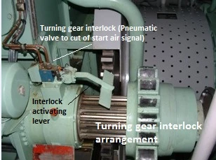
Turning Gear Interlock
The turning gear interlock is a device that prevents the engine from being started if the turning gear is engaged.
What is an interlock?
An interlock is a feature that prevents operation of equipment until the proper safe conditions are met. The interlock prevents the admission of starting air to the engine cylinders when the turning gear is engaged. If the starting air is admitted with the turning gear engaged, the turning gear will be severely damaged, which may harm nearby personnel. Thus, the interlock is necessary.


6.14.2 Safety checks before turning the engine on turning gear.
Need to follow the instructions given by the engine manufacturer regarding the turning gear for type-specific instructions. The following is a common guideline:
When the engine was stopped, before engaging the turning gear, the main Starting air valve has to be completely closed and drained off the staring airline.
-
Indicator cocks must be opened. (Indicator cock is fitted on the cylinder head, which opens the cylinder interior to the outer atmosphere).
-
This indicates any liquid filling in the cylinder; if any liquid comes out, the cause must be investigated and rectified.
-
Opening the indicator cock prevents air compression in the cylinders and reduces T/G motor load.
-
Propeller clearance must be taken in writing from the navigation department. (Propeller clearance means taking written permission from the duty navigation officer to rotate the main engine crankshaft without any obstruction or damage to the propeller, external objects, or personnel).
-
2.Check that all safety devices which are incorporated into the turning gear are functioning properly.
Safety devices include the interlock to prevent starting air opening when the T/G is engaged and the position locking safety pin, which prevents accidental engagement while the engine is in operation.
3. Make sure that there are no personnel in the crank case.
4. Make sure that no tools, devices are left on or in the engine after any maintenance on the engine.
5. Need to ensure correct lubricating oil level and grease where necessary points in the turning gear device.
Check the safety alarms / trips are in operating condition and reset all, such as:
-
Lube oil Pressure / temperature.
-
Cooling water pressure / temperature
-
Fuel oil pressure / temperature.
-
Emergency shut down.
-
Other applicable
Example: Press the EMERGENCY STOP button on the control panel and observe if the safety cut-out on the fuel injection pumps reacts. After this check, press the EMERGENCY STOP RESET button.
6.14.3 Engine Operation
6.14.3.1 Procedure for Preparing the Engine for Starting
Follow the pre-check list (departure check list) for starting of the engine as per the ISM check list. Before starting, the engine operator’s manual should be read and understood for the recommended procedure and type-specific requirements.
Generally, the above-mentioned checks and procedures must be followed as guidelines:
-
All components that have been overhauled should have been correctly reassembled and their functions checked when trying out the main engine. All devices and tools must be removed from the engine.
-
Examples: Injector – feel the jerk of the high-pressure line; Exhaust v/v – check the valve rotation.
-
-
Check the liquid levels of all the tanks in the engine systems including the leakage drain tanks, such as:
-
Fuel oil service / settling tank level & temp.
-
Lube oil sump tank.
-
Cylinder oil daily consumption tank level.
-
Expansion water tank level.
-
Intermediate bearing lube oil level.
-
Stuffing box drain tank level.
-
Scavenge drain tank level.
-
Fuel drain tank level.
-
Piston cooling water tank.
-
-
Check that the fuel regulating linkage moves freely.
-
If any maintenance was carried out in the oil / water systems, those should be vented for air before putting into operation.
-
Start an additional generator and couple it to the main bus bar to provide power for the extra loads.
Check that all the shut-off valves for the engine systems are in the correct position. (e.g., jacket water system valves).

-
Check the engine cooling water system and start the pump. Required checks:
-
Cooling water header tank level.
-
Any leakages in the system.
-
Cooling water engine inlet temperature.
-
Cooling water system general condition.
-
-
Prepare the lube oil system and start the pump. Required checks:
-
Header tank level.
-
Lube oil fine filter condition indicator and pressure.
-
Any leakages in the system.
-
Lube engine inlet temperature.
-
Lube oil system general condition.
-
-
Prepare the fuel system and drain the water in fuel oil service and settling tank. Check the engine fuel oil system and start the pumps. Required checks:
-
Service / settling tank level / temperature.
-
Fuel oil fine filter condition and pressure.
-
Fuel circulating and supply pump filter condition, pressure, and leakages.
-
Fuel viscosity and engine inlet temperature.
-
Fuel oil system general condition.
-
-
Before Opening the air supply to the engine, drain the condensation from:
-
Main air bottle.
-
Air dryers.
-
Control air filters.
-
-
Start up the other systems such as cylinder lubricating system pumps and check/set the pressures to their normal values.
-
Start preheating of the main engine by opening the jacket water to the jacket water preheater and then open steam slowly.
-
Check all the systems for any leakages and operate within normal parameters.
-
Start cylinder pre lubrication.
-
Confirm that all indicator cocks in the engine are opened.
-
Turn the engine more than one revolution using the turning gear and check the motor amperage.
-
Check while turning if any liquid is coming through the indicator cock. If so, investigate the cause (e.g., leaking jacket water, fuel oil from injectors).
-
If even a small amount of liquid comes out of any of the indicator cocks, the T/G must be immediately stopped and the reason investigated/rectified.
-
Take out the turning gear and secure the operating lever.
-
Open the main air shut-off valve on the main air bottle.
-
Set the auxiliary blower control panel selector switch to the automatic position.
-
Check main cooling seawater system and start the pumps. Required checks: Filter condition, pump pressure, and system general condition.
-
Check the boiler and keep it in an automatic position. Required checks: Steam pressure, water level, burner flame condition.
-
Check the other systems related to the main engine and propulsion (e.g., steering gear, control air, stern tube).
-
Select all air compressors to auto mode.
-
Check again to ensure that no personnel are near the flywheel and shaft.
-
Inform the bridge and the duty engineer.
6.14.3.2 Engine Starting
Before the engine is on standby, the engine must be tested on air and fuel by means of ahead and stern direction running after following conditions are full filled:
-
Gradually open main air bottle valve to the main engine.
-
Shut off valve to the air distributor must also be open, if applicable.
-
All the systems related to main engines are in operating condition and stand by condition, free of alarms, shut down and slow down.
-
Inform the bridge and, with their permission, air blow must be done in the control room, monitoring the indicator cocks for any leakages during blow through.
-
If there is fuel, cylinder oil, cooling water or cooling oil leakages, these will be indicated when blowing through. In such a case operation must be immediately stopped.
-
Blow through means introducing starting air to the engine cylinders for a short period while indicator valves are opened.
-
-
If everything is satisfactory, indicator valves to be closed and inform the duty engineer.
-
Try out (check ahead and stern operation of the main engine) the main engine by fuel in either direction. (If M/E bridge control is available, it must be tried out from the bridge as well).
-
Inform the bridge on official standby of the main engine and change over to bridge control. Get the standby counters as required (Fuel oil flow meter, revolution counter, cylinder oil flow meter, etc.).
6.14.3.3 Procedure for Operating the Main Engine
It is preferable to operate the engine at constant power. When the speed and load have to be altered, it should be done as slowly as possible, especially after engine maintenance. During normal running, regular checks have to be made:
-
Regular checks of parameters such as pressures and temperatures. The parameters must be within the manufacturer-accepted range.
-
Liquid flow through sight glasses (Ex. T/C lube oil).
-
Check all systems related to the engine are functioning correctly. Including Pumps, filters, pipelines, and the related systems.
-
Check combustion by observing the color of the exhaust gases.
-
Check the air pressure charge drops through the air filter and air cooler. Excessive resistance will lead to a lack of air to the engine.
-
The fuel has to be carefully cleaned before being used. Open the drain cocks of all fuel tanks and fuel oil filters regularly to drain off any water.
-
Have to regularly monitor and clean the fuel filters according to their differential pressure.
-
Fuel oil service and settling tank temperatures to be correct.
-
Maintain the correct fuel oil pressure and the temperature to inlet the engine.
-
Check that all cylinder lubricators are functioning well.
-
Check the level in all water and oil tanks, as well as all the drainage tanks.
-
Observe the condition of the cooling water. Check for oil contamination.
-
Sight glass is provided in charge the air receiver drains manifolds. Make sure it is clear at all times.
-
Drain the scavenge spaces.
-
The temperature of the running gear should be checked by feeling the crankcase doors. Bearings that have been overhauled or replaced must be given special attention.
-
Listening to the noise of the engine will reveal any irregularities.
-
Centrifuge the sump lubricating oil.
-
Check the inspection glasses in the upper casing of the exhaust valve periodically and note if the air spring cylinder of each exhaust valve is rotating.
-
Avoid critical RPM.
6.14.3.4 Stopped
After the engine has been stopped, the cooling water and lubricating oil pumps should be left running for at least a further 20 minutes in order to allow the temperatures to equalize.
-
Take the main engine control from Bridge to Engine Control Room (make sure fuel lever is in zero position).
-
The starting air supply has to be closed as soon as possible after stopping the engine.
-
The indicator cocks in the cylinder heads are to be opened and the turning gear to be engaged.
-
With post lubrication of the cylinders, the crankshaft must be turned by the turning gear.
-
Turn the engine around 20 minutes after stop. This helps to evenly distribute the residual heat and prevents seizure.
-
Let the cooling water to cool gradually, otherwise sudden cooling may result in thermal stress.
-
Lubricating oil pump should be continued to run for at least a further 2 hours in order to allow the temperatures to equalize gradually.
-
Stop the unnecessary equipment and inform the engineers and crew.
6.14.3.5 Reversed when maneuvering and when at full speed
6.14.3.5.1 Reversing a Slow Speed Engine
The propeller thrust must be reversible for maneuvering and to crash stop the ship. Most vessels require the main engines to be reversible.
-
Start and load additional power generator.
-
Change engine control to the engine control room.
-
Where manually operated auxiliary blowers are fitted, they should be started.
-
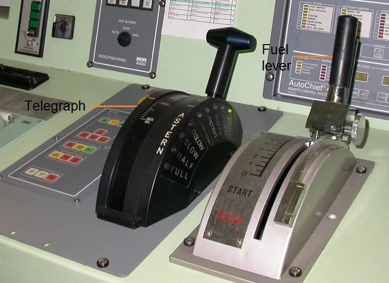
Bring the telegraph to stop position.
-
Shift the fuel level to the stop position. (Engine RPM will reduce).
-
Wait until the RPM of the engine becomes zero.
-
Then bring the telegraph to dead slow astern position.
-
Shift the fuel level to the starting position. (Air will introduce to the engine and crankshaft will rotate to astern direction).
-
When the correct starting RPM is reached, stop starting air and introduce fuel to the engine.
-
Check the running direction.
-
Adjust the fuel lever to maintain correct speed.
6.14.3.5.2 Crash Maneuvering of Ship in Emergency Situation
"Crash maneuvering" is a procedure performed to avoid any kind of collision or accident. Stopping is done by reversing the rotational direction of the Main engine and thereby the propeller.
6.14.3.5.3 Perform Crash Maneuvering
-
Change engine control to the engine control room.
-
Start and load additional power generator.
-
Where manually operated auxiliary blowers are fitted, they should be started.
-
Bring the telegraph to stop position.
-
Shift the fuel level to the stop position. (Engine RPM will reduce).
-
Wait until the RPM of the engine reduces to 40.
-
Then bring the telegraph to Full Astern position.
-
Shift the fuel level to the starting position. (Air will introduce to the engine).
-
When the correct starting RPM is reached, stop starting air and introduce fuel to the engine.
-
Check the running direction.
-
Adjust the fuel lever to maintain correct speed.
-
Note: Crash astern may damage the engine due to thermal shocks as the engine is cool and heats rapidly. To be used only when extremely required.
6.14.4 How engine speed and output power are controlled for normal requirements.
A governor automatically controls engine speed by regulating the fuel supply. The governor must be sensitive to small changes in speed and capable of returning the engine to a set speed, irrespective of changes in load and power.
6.14.4.1 Main types of governors described below:
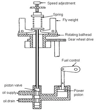
6.14.4.1.1 Mechanical Governor
As shown in the figure below,
-
A flyweight assembly is used to detect engine speed. Flyweights rotate about a vertical axis.
-
Centrifugal force throws the weights outwards, which lifts the vertical spindle and compresses the spring until an equilibrium situation (set speed) is reached.
-
The hydraulic unit is connected to this vertical spindle and acts as a power source to move the engine fuel controls.
- If the engine speed increases, the vertical spindle rises, oil is drained from the power piston, and the resulting movement reduces the fuel supply to the engine, slowing it down.
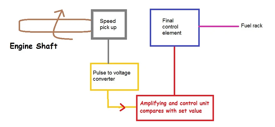
6.14.4.1.2 Electric Governor
The electric governor uses a combination of electronic and mechanical components.
-
Shaft speed is sensed by the speed pick up, and this pulsating signal is converted to voltage and sent to the comparator.
-
The comparator compares the present value with the set value and gives a signal to the amplifier.
-
The amplifier provides enough power to the actuator (Final control element) to move the fuel lever of the engine to get the speed back to the set value.


6.14.5 How engine over speed is prevented
Due to sudden changes in load, the speed of the engine may vary. Although a governor controls speed, the speed might still go out of control, damaging the engine. Thus, over speed trips are used.
The main aim of the over speed trip is to cut the fuel supply to the engine cylinders in case the engine speed rises above a specific level (typically 12% - 18% above rated speed).
Types of Over Speed Trips:
-
Mechanical Type Over Speed Trip
-
Electrohydraulic Overspeed Trip
-
Electro Pneumatic Over Speed Trip
-
Electronic Type Over Speed Trip
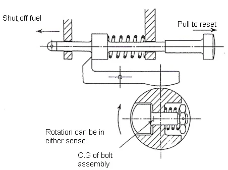
6.14.5.1 Mechanical Type over speed Trip
A simple mechanical over speed trip has a weighted spring-loaded bolt set into the rotating shaft of the engine.
-
The centrifugal force exerted on the bolt exceeds the preset spring force when speed exceeds the limit.
-
The bolt ejects out and strikes a latch, which releases a plunger that shuts off the fuel supply to the engine.
6.14.6 States Typical Normal Temperatures of Exhaust Gas at Discharge from the Cylinder
The temperature measured at the exhaust valves is normally in the range of 320-400 °C at MCR (Maximum Continuous Rating), depending on ambient conditions.
6.14.7 States Typical Normal Temperatures of Exhaust Gas Entering & Leaving a Turbo charging Unit.
Normal Temperatures of exhaust gas entering and leaving a turbocharger unit:
-
Inlet (Entering): 380 – 450 °C
-
Outlet (Leaving): 270 – 320 °C