6.10.1 Sketches typical indicator diagrams for:
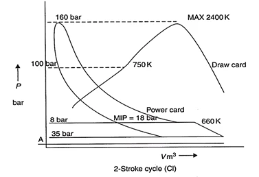
6.10.1.1 A two stroke engine

Typical indicator diagrams for a two-stroke engine show the work done within the measured cylinder in one cycle. The area within the diagram represents the work done. This area is divided by the length of the diagram to obtain a mean height. This mean height, when multiplied by the spring scale of the indicator mechanism, gives the Indicated Mean Effective Pressure (MEP) for the cylinder.
Key points on the diagram:
A. Ignition
B. Pressure-Volume Working Diagram
C. Ignition Stroke
D. Draw Diagram
E. Top Dead Centre (TDC)
F. Bottom Dead Centre (BDC)
G. Pcomp
H. Pmax
I. Opening of Exhaust Valve
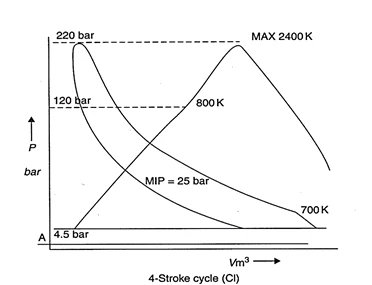
6.10.1.2 A four stroke engine

6.10.2 Explains the problems of obtaining indicator diagrams from slow-speed, medium-speed and high-speed engines
An engine indicator which is suitable for taking indicator diagrams is typically reliable up to rotational speeds of about 300 rev/min.
For medium-speed and high-speed engines, it may be impractical to use a normal engine indicator due to the high velocities of parts causing vibrations in springs or drive mechanisms. If other means are not available, power in the engine may be related to peak or maximum pressure in the cylinder.
Generally, only slow speed engine builders provide mechanical indicator drum drive mechanism in the engine.

6.10.3 Peak pressures are sometimes measured which give an indication of engine power and performance
The power in the engine is related to the peak or maximum cylinder pressure; this is measured using a peak pressure indicator. This can be a mechanical device, using compression of a spring to indicate pressure or a pressure transducer linked to a digital read out. This should be done at between 85 -100% MCR (Maximum Continuous Rating). It is more accurate to use the difference between the peak and the compression pressure when assessing cylinder powers and attempting to balance the engine.
In small engines, only the peak pressure is measured, and it is an indication of power and performance of the engine unit.
6.10.4 Develops the expression: work = pressure x volume, to produce an expression for the power of a diesel engine in terms of M.E.P., number of cylinders, length of stroke, diameter of piston and R.P.M.

Force
Force is the influence, which tends to change the motion or direction of a body at rest or in motion.
Force = Pressure x Area
Nm^{-2} x m^2
N
Force is measured in Newton (N)
Work
Work is the use of energy to overcome resistance. Work is done when a force is applied on an object to move it through a distance.
Work = Force x Distance
N x m
Nm
Since Force is measured in Newton (N) and distance in metres (m), the units of work are Newton metres (Nm).
One Newton metre is defined as one Joule (J). Joule: It is equal to the energy transferred (or work done) to an object when a force of one newton acts on that object in the direction of its motion through a distance of one meter (1 Newton meter or N.m).
Power
Power is the amount of work done or energy expended in a given time. A Watt (W) is the unit of measurement of power.
One watt is defined as the energy expended or work done at the rate of one Joule per second.
Power = Work = Force x Distance (Joule)
Time Time (second)
Indicated Power (IP) Expression
The mean effective or 'average' pressure (MEP) can now be used to determine the work done on the cylinder:
Work per Cycle = MEP x Area x Stroke Length
To obtain a measure of power, it is necessary to determine the rate of doing work, i.e., multiply by the number of power strokes in one second.
The indicated power is calculated using the mean effective pressure.
IP = P x L x A x N
Where:
-
IP = Indicated power (Watts) {1kW = 1000 Watts}
-
P = Mean effective pressure (kg/cm^2)
-
L = Length of piston stroke (Meters)
-
A = Cross sectional area or cylinder bore (Square meters)
-
N = Number of working strokes per second (revs/second)
For a multi-cylinder engine, it would be necessary to multiply the result by the number of cylinders.
6.10.5 Calculation of indicated power
Given Data:
-
Area of diagram = 840 mm^2
-
Length of diagram = 105 mm
-
Mean height of diagram = 8 mm
-
Spring constantly = 200 kN/m^2 per mm
-
Diameter of cylinder = 960 mm (Radius 0.48 m)
-
Stroke of piston (L) = 2.5 m
-
Engine Speed = 90 RPM = 1.5 revs/sec
Step 1: Calculate Mean Indicated Pressure (MIP or P)
MIP = 8 x 200 = 1600N/m2
Diameter of cylinder= 960 mm (radius 0.48m)
Stroke of piston = 2.5m
Step 2: Calculate Work per Cycle
Work per cycle (or revolution) = 1600 x π x 0.48x0.48 x 2.5 = 2895 kNm or kJ
Step 3: Calculate Indicated Power (IP).
E. G. 90 RPM = 1.5revs/sec.
2895 X 1.5 = 4343kW
This process is repeated for each cylinder on the engine.
This process is repeated for each cylinder on the engine to find the total Indicated Power of the engine.
6.10.6 States typical compressions and maximum pressures for slow-, medium- and high-speed engines
Maximum compression pressures for the slow speed engine